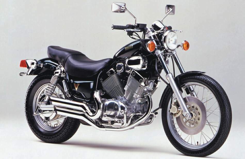
Honda Virago 250 Owners Manual
Hand brake lever The hand brake lever 1 is mounted on the handlebars on the right and actuates the front wheel brake. The adjusting screw A can be used to change the basic position of the hand brake lever (see “Maintenance”). 1 A Short circuit button The short circuit button 2 turns off the engine. When pressing this button, the ignition circuit is short-circuited. 2 Headlamp switch (XCF-W) In this model the headlamp is switched on with the pull switch 5. 5 Flasher switch The flasher switch is a separate unit and is mounted on the left portion of the handlebar. The wire harness is designed in a way that whenever you want to use your bike off-road, you can dismount the entire turn indicator system without affecting the function of the remaining electrical system.
Honda Virago 250 Owners Manual Pdf
Flasher left Flasher right OPERATION INSTRUMENTS » ENGLISH 7 1 2 3 4 5 Starter button Pushing the red starter button 1 will actuate the E-starter. Emergency OFF switch (EXC-F Australia) The red emergency-OFF switch 2 is arranged adjacent to the throttle grip. In this position, the E-starter is operational and the engine can be started. In this position, the E-starter and ignition circuits are interrupted.The E-starter cannot be actuated, and the engine will not start, not even if you attempt to start it with the kickstarter.
Pushing the black starter button 3 will actuate the E-starter. Indicator lamps The green control lamp 4 flashes in the same rhythm as the flashing indicator when the indicator is working. The blue control lamp 5 lights up when the high beam is on.
TEST All of the display segments briefly light up for the display function test. Electronic speedometer The display in the electronic speedometer is activated as soon as you press a button on the speedometer or an impulse is received from the wheel sensor. The display lights up when the engine is running. The display is cleared if no button is pressed for 1 minute or no impulse is received from the wheel sensor. The button is used to change between display modes.
GE Appliances' owner's manuals page offers specific use and care guides and installation instructions on GE Appliances as well as Quick Specs and Energy. Oct 8, 2010 - Hi there, Save hours of searching online or wasting money on unnecessary repairs by talking to a 6YA Expert who can help you resolve this. Ge rapid clean 3 manual. Oct 29, 2015 - If the instructions are gone, you'll notice that the temperature dial has a. Sheets, and so on) and turn on self clean. Maximum ovens will lock,. Troubleshooting Tips. Installation Instructions. Customer Service. The fiberglass insulation in self-clean ovens gives off a very small amount of.
The + and – buttons are used to control various functions Incoming search terms:. This instruction sheet references Service Manual information. A Service Manual for your model motorcycle is required for this installation and is available from a Harley-Davidson Dealer. Kit Contents See Figure 2 and Table 1.
INSTALLATION 1. Position the vehicle on a motorcycle lift table. To prevent accidental vehicle start-up, which could cause death or serious injury, remove maxi-fuse before proceeding. Refer to the Service Manual and follow the instructions given to remove the Maxi® Fuse. Raise the vehicle on the lift table to allow access to the lower front portion of the frame. 2008+ 2007 7 8 11 3 3 4 4 12 5 5 1 1 9 2 2 10 6 6 9 9 11 13 is02652c 8. Two-pin voltage regulator connector (2007 only) Voltage regulator 2.

Voltage regulator attaching screws (2) Cable strap (2 for 2007, 1 for 2008 and later) 10. Lower voltage regulator cover (2007 only) Voltage regulator bracket 4. Bracket screw to engine crankcase (2) Oxygen sensor connector 12. Crank position sensor connector (2007 only) Voltage regulator caddy 6. Voltage regulator caddy cover Horn connectors (some 2008 and later models) 7.
Four-pin voltage regulator connector (2007 only) Figure 1. Original Equipment Voltage Regulator NOTE For 2007 models: The ground wire on the voltage regulator must be re-attached at the original location when re-installing the voltage regulator to ensure adequate ground. For ALL models: See Figure 1. Remove and discard the voltage regulator caddy cover (6) from the regulator bracket (3) and caddy (5). For 2007 models: In addition, remove the lower voltage regulator cover (10). Remove and retain the hex socket head screw (4) at the top left of the bracket For 2007 models: In addition, disconnect the ground wire. Free the cable straps (9) from the regulator bracket, beneath the regulator.
Remove the two hex socket head screws with washers (2) retaining the voltage regulator to the bracket. Remove and save the regulator, but discard the screws. Remove and retain the screw (4) at the top right of the regulator bracket. Remove the bracket from the engine. For 2008 and later models: Free the strap (9) that ties the jiffy stand wiring to the voltage regulator bracket.
Unfasten the three-way jiffy stand sensor connector and the two-way crank position sensor connector 79 (12) from the T-studs on the back of the regulator bracket (3). Discard the bracket. Disconnect both plugs from the back of the voltage regulator (1). For 2007 models: Unfasten the four-way (7) and two-way (8) voltage regulator connectors from the T-studs on the back of the regulator bracket (3), and discard the bracket. Disconnect the voltage regulator (1) at both connectors.
For 2008 and later models: Unclip the two-way O 2 (oxygen) sensor electrical connector 138 (11) from the voltage regulator caddy (5). For 2007 models: Unfasten the two-way crank position sensor connector 79 (12) from the voltage regulator caddy (5). Remove the caddy from the vehicle frame. For 2007 models: Unclamp the bottom of the caddy from the engine mount spacers. For ALL models: Unhook the top clips from around the tabs on the front of the engine casting. Remove the original equipment (O.E.) caddy from the vehicle frame, and discard it. Incoming search terms:.
Yamaha xv250 virago service repair manuals on 1989 2005 yamaha xv250 virago service repair manual service repair manual yamaha virago 250 xv250 1988 2006. Service your yamaha xv250 virago v star 250 with a cyclepedia service manual features full color photographs wiring diagrams and step by step procedures. Yamaha virago 250 service repair manual pdf 89 05 yamaha virago xv1100 digital workshop repair manual 1986 99 yamaha virago xv535 digital workshop repair manual 1987.
Honda Virago 250 Owners Manual Download

Basicly this manual book shared for yamaha xv250 aka virago 250 aka v star 250 owners to help them know about their motorbike but chinesee copy of this bike that. Collections of yamaha bikes workshop service manuals repair manual spare parts catalogs and owners manuals.